

How To Set Up An Arterial Line
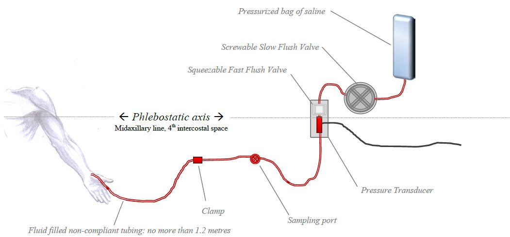
The arterial line pressure transducer setup
The arterial line pressure transducer setup
This chapter is vaguely relevant to Section G7(3) of the 2017 CICM Principal Syllabus, which asks the exam candidate to"draw the invasive and non-invasive measurement of claret pressure, including limitations and potential sources of error". It is also loosely associated with Section G7(ii),"describe the principles of measurement, limitations, and potential sources of
error for pressure transducers, and their scale". Information technology represents a summary of the important concepts for the purpose of rapid revision, with a focus on arterial blood force per unit area measurement.
The need for such a summary is not clear in the context of the CICM Role I exam, as the examiners have only ever interrogated the trainee's understanding of these matters in one case, in Question ii from the first paper of 2022. "Hydraulic coupling and transducers" formed an of import part of the answer there. Overall, the field of study matter seems like something foundational to ICU exercise, and in his attempt to explain these issues to himself the writer had written extensive notes on the field of study early on in his career. Information technology seemed wasteful to destroy them, and they are reproduced here for sentimental reasons as much as for educational ones.
In summary, the components of the measurement system and their characteristics are every bit follows:
- An intra-arterial catheter
- Kink-resistant, biologically inert, incompressible
- Accesses the arterial circulation and provides the interface between the arterial blood and the circuit fluid
- Fluid-filled tubing
- Produces the hydraulic coupling between the arterial circulation and the pressure level transducer
- Access points to allow sampling
- Flush valve
- Fluid in the tubing
- Incompressible
- Usually, normal saline or
- Under pressure from the force per unit area bag to prevent blood refluxing into the line
- Counterpressure fluid bag
- Pneumatically pressurised to ~ 300mmHg to sufficiently counteract systemic arterial pressure
- Force per unit area transducer
- Wheatstone span piezoresistive transducer which converts force per unit area into a modify of electrical current
- Indicate conditioning and monitoring software
- Filters the raw bespeak from the transducer
- Converts it into a human-readable waveform
- Records the information in a storage medium for review
The fluid-filled transducer arrangement used for this is the same every bit would be institute in any other organisation measuring the pressure in whatsoever other fluid-filled compartment (primal veins, cognitive ventricles). The physics behind this is discussed at great length in the chapter on "Pressure transducers for haemodynamic measurements" and "Resonance, damping and frequency response". These and other entries under the heading "Principles of Pressure Measurement" represent a redux of this chapter and add picayune to the learning process, in the aforementioned manner that a four-60 minutes manager'due south cut adds fiddling to the content of a motion-picture show which retains all of its positive qualities when cut by 50% for cinema release.
Arterial Line Transducer Setup
The arterial pressure moving ridge travels at six-10 metres/sec. The cannula in the artery is connected to the transducer via some not-compliant fluid-filled tubing. The transducer is usually a soft silicone diaphragm attached to a Wheatstone Span. It converts the pressure change into a alter in electric resistance of the excursion. This can be viewed as waveform.
Priming the non-compliant pressure tubing
The thought is that the fluid in the tubing transmits the pressure wave to the transducer - The whole principle rests on a continuous cylinder of saline connecting the avenue to the pressure transducer. The design and engineering science characteristics of this tubing has a significant influence on the function of the whole transducer organization.
Damping
Without restating the fabric discussed in the chapter on resonance and damping, one tin simply say that "damping is anything that has a "shock absorber" upshot on the art line. Air bubbles, long tubing, narrow tubing or soft compliant tubing – all of these absorb some of the forcefulness of the pulse moving ridge decreasing the amplitude of the oscillations. This is ane of the reasons normal Four tubing is not used to set upwards an arterial line transducer kit: the IV tubing is too soft and compliant. An excessively rubberband length of tubing volition cause damping past absorbing the energy of the pressure wave, wasting it on deforming the walls of the transducer set (which volition depend on the viscosity of the tubing textile). The professional-sounding way to express this concept in the examination would be to say that rubberband tubing increases the damping coefficient. To modify a diagram from Gardner (1981), which describes the relationship between damping coefficient and resonant frequency on art line waveform interpretation:

So: taking an otherwise acceptable arterial line trace and increasing the damping by increasing the elasticity of the tubing will take information technology into an unuseable overdamped territory. Overdamping results in a slurred waveform with overestimation of the diastolic and underestimation of systolic; however, the MAP value is usually preserved. In contrast, a kinked or clogged art line volition see MAP systolic and diastolic all trending towards zero.
Resonance
The fluid-filled system has a sure natural frequency of resonance. In an ideal organisation with some sort of perfectly inelastic tubing, the major determinant of this natural frequency is the length of the tubing: the longer the tubing, the lower the natural frequency. The patient's pulse oscillation is usually a fairly depression-frequency phenomenon, and as the tubing length increases, the natural frequency approaches the patient'southward pulse wave frequency. The organization then resonates, amplifying the signal. Thus, the longer the tubing, the more resonance in the system, and consequently the system will be underdamped. For the same reason, the tube lumen should always be no smaller than 1.5mm. To use the aforementioned diagram from Gardner:

So, as you can see, increasing the length of this platonic inelastic tubing will also pull the transducer set into a territory where it loses its clinical utility. Nevertheless, no tubing is "platonic" - it cannot be a rigid glassy pipe in guild for it to remain clinically usable. And so: what is the net effect of increasing tubing length in the real world?
Net effect of tubing length on resonance and damping coefficient:
why only 1.two meters of tubing?
Aye, length of tubing tin increase the resonance, and information technology can also cause overdamping. The longer the tubing, the lower the natural frequency of the transducer system, so theoretically the more than resonance. On the other mitt, an excessively elastic length of tubing will cause damping by absorbing the free energy of the pressure level moving ridge. In other words, longer tubing increases the damping coefficient and lowers the natural frequency. To put this on Gardner's diagram:

Zeroing and levelling the art line
Zeroing and levelling are occasionally used interchangeably, but they are not the same thing. They tend to occur together in the clinical setting, merely the terms describe unlike processes. Zeroing exposes the transducer to atmospheric pressure via an open up air-fluid interface, and levelling assigns this zero reference point to a specific position on the symbolic fluid-filled column that is the patient'southward body.
"Zeroing"can be defined equally "the apply of atmospheric pressure equally a reference standard against which all other pressures are measured". The canonical college definition is "a process which confirms that atmospheric pressure results in a nada reading past the measurement system". The device is zeroed when the air-fluid interface is opened to atmospheric pressure (otherwise it would read diastolic blood pressures of ~ 760mmHg). Atmospheric pressure varies fiddling between the intensivists' heart level and the supine patients' aortic root level, and so strictly speaking the zeroing of an arterial line can accept identify with the transducer lying anywhere. Re-zeroing must occasionally take place every bit both the transducer and the atmospheric pressure will gradually drift abroad from the scale point.
"Leveling" can be defined as "the selection of a position of interest at which the reference standard (nil ) is prepare". The canonical college definition is "a process which determines the position on the patient you wish to be considered to exist your zero." For reasons of convenience this tends to happen at the same time as zeroing the system to atmospheric pressure (which also sets the reference "0 mmHg" standard), but theoretically one could zero the transducer to temper and then swing it wildly all around the room before levelling information technology against a reference point on the frightened patient.
The organization is conventionally "levelled" at the phlebostatic axis, which is a reference level nosotros accept used since probably 1945. The phlebostatic centrality corresponds roughly with the position of the right atrium and aortic root, and his level has more often than not been accustomed every bit the ideal reference level for measure the pressure of the claret returning to the heart. It was therefore adopted equally the reference level for CVP measurement. For arterial pressure measurements, at to the lowest degree since 2001 or so we accept as well been levelling the arterial lines at the phlebostatic centrality. Prior to that, some units levelled their arterial lines at the level of the catheter insertion site. The specific reference bespeak for the arterial transducer is really the aortic root, but because it is very close to the right atrium the two reference levels are essentially the same.
The scientific basis for these reference points is murky, and relates vaguely to the idea that these are besides the reference points from which your own force per unit area transducers (the atrial and arterial baroreceptors) "measure" the pressure for the purpose of maintaining cardiovascular homeostasis. This concept, in turn, relates to the idea of there beingness a "hydrostatic indifference indicate" where pressure level and vascular wall stress remain stable irrespective of changes in body position, and which appears to be somewhere effectually the right atrium. At that place are actually distinct hydrostatic indifference points for the venous and arterial circulation, and the correct atrium is probably not where they are in the normal human being (that correct atrial location was determined in the 1930s by rotating the bodies of dead animals), but to discuss this hither would represent an unforgivable digression. More detail is available in the affiliate dealing with the physiological responses to changes in posture. For the purposes of day-to-twenty-four hours employ, the arterial line should be zeroed at the "phlebostatic axis", any that is.
For every 10cm below the phlebostatic axis, the art line will add together 7.4mmHg of force per unit area.
One may sometimes exist interested in levelling the arterial line at another point. Substantially, the level at which you nothing the arterial line volition measure the arterial pressure at that level. Which means that if your patient is in some sort of unconventional position (eg. sitting bolt upright) yous may wish to measure at the level of the tragus instead. An art line levelled at the level of the external auditory meatus will measure the arterial pressure in the Circumvolve of Willis, which is a representation of cognitive perfusion pressure. Diverse eminent society guidelines recommend that for the use of cerebral perfusion pressure as a therapeutic target, the reference level should be somewhere around the middle cranial fossa. Whether this matters or not is a subject of some debate.
Flushing the art line
Plain, using heparinised saline improves accurateness somehow, simply does not prolong patency.About centres have abandoned this practice considering of the increased risk of HITS. The normal rate of menstruum is 3ml/hour, just to keep the catheter from clotting. The affluent charge per unit of the fast flush is thirty-60ml/min, so in absence of a good cannula, ane tin infuse the patient with a litre of flush fluid every 15-30 minutes.
References
I humbly thank Vincent Chen (President of AACN, I think) for helping me bring some sort of lodge and accuracy to this set of notes. The quality of this resources is enhanced by his contribution.
Gardner, Reed Thousand. "Direct blood pressure level measurement-dynamic response requirements."Anesthesiology 54.3 (1981): 227-236.
From Bersten and Soni's" Oh's Intensive Care Manual", sixth Edition; plus McGhee and Bridges Monitoring Arterial Blood Pressure: What You May Not Know (Crit Care Nurse April 1, 2002 vol. 22 no. ii 60-79 )
Scheer,Perel and Pfeiffer.Complications and risk factors of peripheral arterial catheters used for haemodynamic monitoring in anaesthesia and intensive care medicine. Crit Care. 2002; six(3): 199–204.
For those who similar hardcore physics, this fantabulous resource will be an enormous source of amusement. It appears to be a free online textbook of anaesthesia.
LITFL also link to this comprehensive FRCA cocky-assessment document:
Abby Jones, Oliver Pratt; Concrete PRINCIPLES OF INTRA-ARTERIAL BLOOD Pressure MEASUREMENT - Amazement TUTORIAL OF THE WEEK 137 eighth JUNE 2009
McCanny, Peter, et al. "Haemodynamic monitoring and direction." (2013). PACT, ESICM
This FRCA study document on arterial pressure monitoring is a goldmine of detailed data.
Lodato RF, Schlichting R: "Arterial force per unit area monitoring. Arterial catheterization: complications." In Principles and Practice of Intensive Care Monitoring. Volume Part III. 2nd edition. Edited by Tobin MJ. New York: McGraw Colina; 1998::733-756.
Winsor, Travis, and George E. Burch. "Phlebostatic Axis and Phlebostatic Level, Reference Levels for Venous Pressure Measurements in Man." Experimental Biology and Medicine 58.2 (1945): 165-169.
McCann, Ulysse G., et al. "Invasive arterial bp monitoring in trauma and disquisitional intendance: Effect of variable transducer level, catheter access, and patient position." CHEST Journal 120.4 (2001): 1322-1326.
Thomas, E., M. Czosnyka, and P. Hutchinson. "Calculation of cerebral perfusion pressure in the management of traumatic brain injury: joint position statement past the councils of the Neuroanaesthesia and Disquisitional Intendance Society of Great Uk and Ireland (NACCS) and the Gild of British Neurological Surgeons (SBNS)." British journal of anaesthesia (2015): aev233.
Gondringer, N., and J. D. Cuddeford. "Monitoring in anesthesia: clinical application of monitoring central venous and pulmonary avenue pressure (standing education credit)." AANA periodical 54.one (1986): 43-56.
Source: https://derangedphysiology.com/main/cicm-primary-exam/required-reading/cardiovascular-system/Chapter%20758/arterial-line-pressure-transducer-setup
0 Response to "How To Set Up An Arterial Line"
Post a Comment